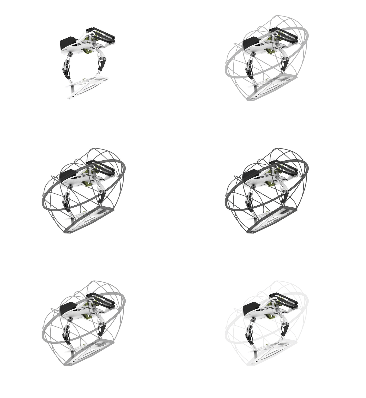
HOPPA:
JUMPING ROBOT
Not only is jumping an energy efficient way of travelling, but it also enables us to create a robot that adapts to rough terrains.
Hoppa is a monopod jumping robot.
With a jumping capability of 300 mm in height and width (simultaneously) and a weight under 300 g, Hoppa presents a great potential for the exploration of new and tough environments. Plus, its build cost does not surpass £100!
Pilar Zhang Qiu
01 TIMELINE

RESEARCH: BIOMIMICRY
- Self-righting in
Nature
- Theory of Jumps /
Mechanics of Joints
- Morphological
Analysis
- Initial Concept
3D MODELING AND FAILURE ANALYSIS
- IP54
- Failure Analysis
- Component Sourcing
- Full CAD Model
- Fixtures and Assembly
- Optimisation
TECHNICAL
ANALYSIS
- Requirements and Initial
Energy Calculations
- Jumping and Trigger
Mechanism/Components
- Drive Design: 2 in 1
Main tasks:
Technical skills
Design skills
02 MEET HOPPA:
THE JUMPING ROBOT

TRY ME!
Interactive 360º Model

SO, WHO IS HOPPA?
1 ) SELF-RIGHTING | LEARNING FROM NATURE

Realistically, a robot will rarely land on its foot. This affirmation becomes even truer in rough terrains. Therefore, a self-righting mechanism is required so that no human interaction is needed for the robot to operate in a multiple-jump loop.
The structure of the shell was inspired by Gomboc, a product of biomimetics, that mimics how turtles self-right when they fall upside down.
For more information: See p. 3 &10 in PDF.

2 ) DRIVE | 2 PATHS, 1 MOTOR
The main feature of the internal mechanism implemented in the drive is its ability to fulfil different tasks depending on the direction of rotation of the motor. This is achieved thanks to the U-shaped double-way clutch shown on the left.
If the motor rotates to the anticlockwise, then the pinion gear will also rotate in this direction and therefore force the middle gear to engage with the left path, leading to the winch.
In the case of rotating clockwise, the middle gear will transmit this turning movement to the right route, which activates the yaw control.
When creating this mechanism, I applied the theory behind an epicyclic gear set with a fixed annulus or ring, also called a planetary arrangement. (See PDF for explanation)
For more information & calculations: See p.7-8 in the PDF.

U-shaped double-way clutch. Winch path engaged (top-left), isometric view (top-right) and explanation (bottom). Blue arrows represent velocities due to turning. Blue ones represent velocity due to spinning.
Motor


Sometimes, the control can get 'stuck' in irregular environments. For example, Hoppa can fall between two rocks that stop it to go back to its original upright position.
The 'Yaw Control' mechanism was created to deal with this issue. This system shifts the centre of gravity of the robot with the help of a satellite slider-crank mechanism attached to a weight.
While one side of the crank is connected to the drive, the other one is attached to the weight. As the weight is located within a linear guide, the weight will follow the satellite gears and move along the slider, shifting the centre of mass from the centre to the left or the right.
For more information & calculations: See p.7-8 in the PDF.
3 ) UNSTABLE CONFIGURATIONS | SHIFTING THE CENTER OF MASS
03 RENDERS
For more information, access the technical report
 |  |  |  |
|---|---|---|---|
 |  |  |  |